Denavit–Hartenberg Parameters
A commonly used convention for selecting frames of reference in robotics applications is the Denavit and Hartenberg (D–H) convention which was introduced by Jacques Denavit and Richard S. Hartenberg. In this convention, coordinate frames are attached to the joints between two links such that one transformation is associated with the joint, [Z], and the second is associated with the link [X]. The coordinate transformations along a serial robot consisting of n links form the kinematics equations of the robot,
[T]=[Z1][X1][Z2][X2]....[Xn-1][Zn][Xn].
where [T] is the transformation locating the end-link.In order to determine the coordinate transformations [Z] and [X], the joints connecting the links are modeled as either hinged or sliding joints, each of which have a unique line S in space that forms the joint axis and define the relative movement of the two links. A typical serial robot is characterized by a sequence of six lines Si, i = 1,...,6, one for each joint in the robot. For each sequence of lines Si and Si+1, there is a common normal line Ai,i+1. The system of six joint axes Si and five common normal lines Ai,i+1 form the kinematic skeleton of the typical six degree of freedom serial robot. Denavit and Hartenberg introduced the convention that Z coordinate axes are assigned to the joint axes Si and X coordinate axes are assigned to the common normals Ai,i+1.
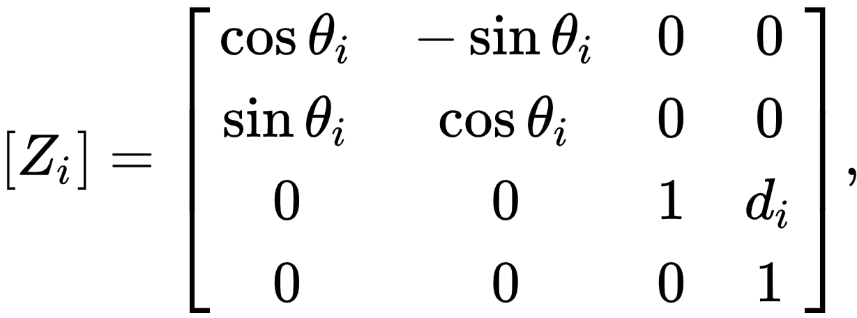
This convention allows the definition of the movement of links around a common joint axis Si by the screw displacement,

where θi is the rotation around and di is the slide along the Z axis—either of the parameters can be constants depending on the structure of the robot. Under this convention the dimensions of each link in the serial chain are defined by the screw displacement around the common normal Ai,i+1 from the joint Si to Si+1, which is given by

where αi,i+1 and ri,i+1 define the physical dimensions of the link in terms of the angle measured around and distance measured along the X axis.
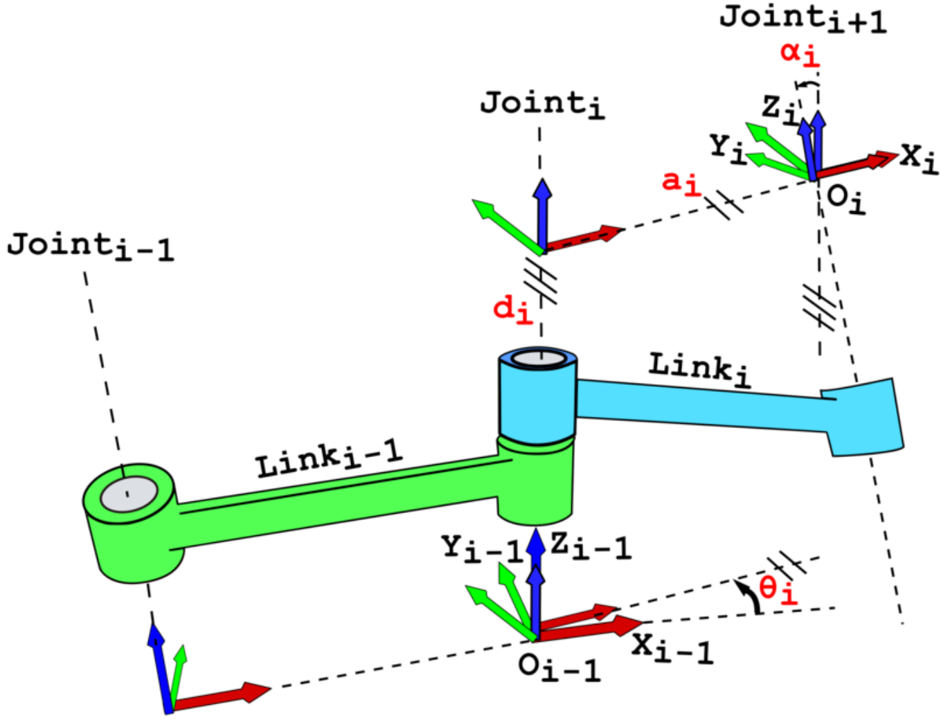
In summary, the reference frames are laid out as follows:
- the z-axis is in the direction of the joint axis
- the x-axis is parallel to the common normal: xn=zn x zn-1 (or away from zn-1) If there is no unique common normal (parallel z axes), then d (below) is a free parameter. The direction of xn is from zn-1 to zn, as shown in the video below.
- the y-axis follows from the x- and z-axis by choosing it to be a right-handed coordinate system.
- d: offset along previous z to the common normal
: angle about previous z, from old x to new x
- r: length of the common normal (akaa, but if using this notation, do not confuse with
). Assuming a revolute joint, this is the radius about previous z.
: angle about common normal, from old z axis to new z axis
- the xn-axis is perpendicular to both the zn-1 and zn axes
- the xn-axis intersects both zn-1 and zn axes
- the origin of joint n is at the intersection ofxn and zn
- yn completes a right-handed reference frame based onxn and zn
Four parameters

The following four transformation parameters are known as D–H parameters:
A visualization of D–H parameterization is available:
There is some choice in frame layout as to whether the previous x axis or the next x points along the common normal. The latter system allows branching chains more efficiently, as multiple frames can all point away from their common ancestor, but in the alternative layout the ancestor can only point toward one successor. Thus the commonly used notation places each down-chain x axis collinear with the common normal, yielding the transformation calculations shown below.
We can note constraints on the relationships between the axes:
Denavit–Hartenberg matrix
It is common to separate a screw displacement into the product of a pure translation along a line and a pure rotation about the line,[5][6] so that
and,
Using this notation, each link can be described by a coordinate transformation from the concurrent coordinate system to the previous coordinate system.
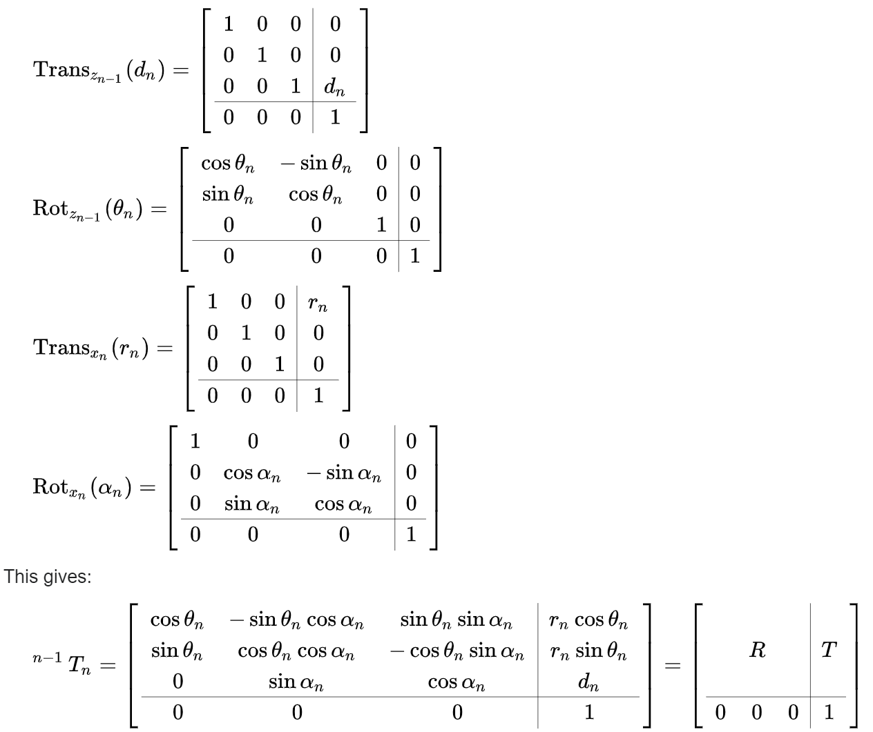
Note that this is the product of two screw displacements, The matrices associated with these operations are:

where R is the 3×3 submatrix describing rotation and T is the 3×1 submatrix describing translation.
In some books, the order of transformation for a pair of consecutive rotation and translation (such as dnand ) is replaced. However, because matrix multiplication
order for such pair does not matter, the result is the same. For example:
 Previous
